With every new batch we will issue our measuring report. The dimensions mentioned on the drawing are measured as you can see in the table below. We random check according to AQL.
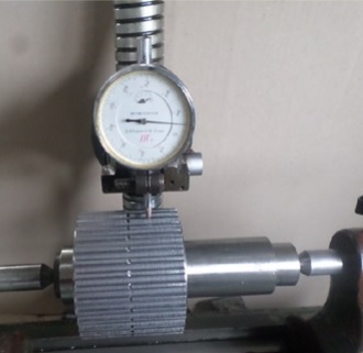
The precise center bores are measured with go/no-go gauge plugs. We even measure both the top circle and axial runout as you can see in both the table below and the picture at the bottom of this page.
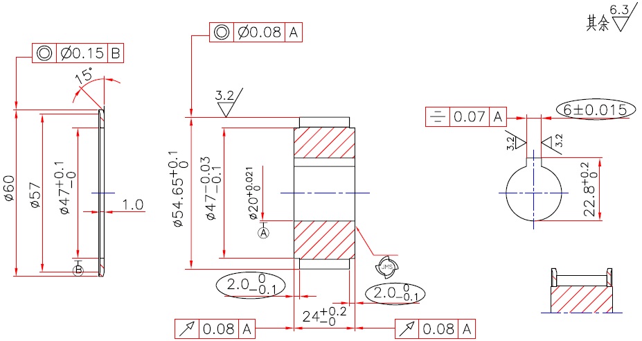
Example drawing
| No. | Inspection item | Checking tool | Dimension (tolerance) | Sample 1 | Sample 2 |
| 1 | Number of teeth | Visual | 22 | OK | OK |
| 2 | Outside diameter | Micrometer | Ø54,65 (+0,1/0) | 54,74 | 54,74 |
| 3 | Inside bore diameter | Gauge plug (go/no-go) | Ø20 (+0,021/0) | OK | OK |
| 4 | Diameter for mounting the flange | Micrometer | Ø47 (-0,03/-0,1) | 46,95 | 46,95 |
| 5 | Spigot depth | Depthometer | 2 (0/-0,1) | OK | OK |
| 6 | Keyway width | Width gauge (go/no-go) | 6 (+0,015/-0,015) | OK | OK |
| 7 | Keyway depth | Vernier caliper | 22,8 (+0,2/0) | 22,84 | 22,84 |
| 8 | Keyway symmetry | Symmetric gauge | 0,07 | OK | OK |
| 9 | Total length | Vernier caliper | 24 (+0,2/0) | 24,12 | 24,08 |
| 10 | Flange diam. ; thickness ; zinc plating | Vernier caliper | Ø60 ; 1 | OK | OK |
| 11 | Top circle runout | Mandrel, deflection instrument, dial gauge | 0,08 | 0,04 | 0,04 |
| 12 | Axial runout | Mandrel, deflection instrument, dial gauge | 0,08 | 0,03 | 0,05 |
| 13 | Teeth profile | Projection | HTD 8M | OK | OK |
| 14 | Roughness | Roughness reference and visual | Ra 3,2 ; Ra 6,3 | OK | OK |
| 15 | Appearance | Visual | Color, wrong machining, corrosion, correct marking, cracks, scratches and other defects | OK | OK |
Measurement of the top circle runout
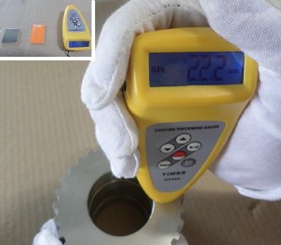
Our sophisticated anodizing depth measuring equipment is depicted below, we will mention the outcome for you on each measuring report.